2005-2015 Audi Q7
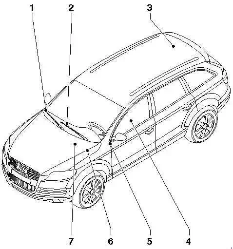
- On right in dash panel
- Left-hand drive models: in centre of dash panel / Right-hand drive models: in driver's footwell
- On right in luggage compartment
- Under driver seat
- On left in dash panel
- On left in plenum chamber.
- In rear left of engine compartment (gasoline / diesel)
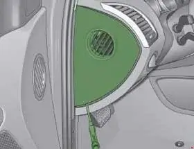
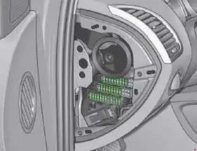
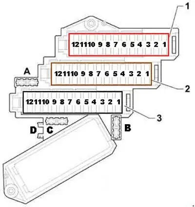
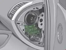
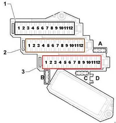
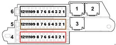
Fuse assignment in fuse box, left dash panel
{banner_news1}
| No. | A | Description |
|---|---|---|
| A | - | - |
| B | 10 | June 2009→: Main fuse for optional equipment |
| C | - | - |
| D | - | - |
| Fuse carrier 1 | ||
| 1 | 5 |
June 2010→: Voltage stabiliser
|
| 2 | 5 |
June 2010→: Relay for automatic anti-dazzle interior mirror
|
| 3 | 7,5 |
June 2010→: Control unit for information electronics 1
|
| 4 | 5 | →May 2010: Tyre pressure monitor control unit |
| 5 | 20 | Auxiliary heater control unit |
| 6 | 10 | LHD: Driver seat lumbar support adjustment switch |
| 10 | RHD: Front passenger seat lumbar support adjustment switch | |
| 7 | 35 | LHD: Driver door control unit Driver side window regulator motor Rear left door control unit Rear left window regulator motor |
| 35 | RHD: Front passenger door control unit Rear right window regulator motor Front passenger side window regulator motor |
|
| 8 | 15 | LHD: Driver door control unit Rear left door control unit (→May 2008) |
| 15 | RHD: Front passenger door control unit Rear right door control unit |
|
| 9 | 5 |
→May 2008: Energy management control unit
|
| 5 | June 2010→: From Tyre pressure monitor control unit |
|
| 10 | 30 | LHD: Entry and start authorisation control unit Entry and start authorisation switch |
| 5 | RHD: Media player in position 1 (→June 2009) Media player in position 2 (→June 2009) CD changer (→May 2010)
DVD player (→May 2010)
MiniDisc player (→June 2009) Video recorder and DVD player (→June 2009) Connection for external audio sources (→June 2009) |
|
| 11 | 10 | LHD: Steering column electronics control unit |
| 10 | RHD: Rear Climatronic operating and display unit Rear fresh air blower control unit |
|
| 12 | 5 | LHD: Interior monitoring sensor Alarm horn |
| 5 | RHD: Comfort system central control unit | |
| Fuse carrier 2 | ||
| 1 | - | - |
| 2 | - | - |
| 3 | 15 |
June 2009→: Front left seat ventilation control unit
|
| 4 | 30 | Wiper motor control unit Windscreen wiper motor |
| 5 | 5 | Light/rain sensor |
| 6 | 25 | Dual tone horn relay High tone horn Low tone horn |
| 7 | 30 | LHD: Onboard supply control unit |
| 25 | RHD (June 2010→): 12 V socket 3 12 V socket 4 |
|
| 8 | 25 | LHD: Onboard supply control unit |
| 20 | RHD: Cigarette lighter |
|
| 9 | 25 | LHD: Onboard supply control unit |
| 25 | RHD: 12 V socket 12 V socket 2 |
|
| 10 | 10 | LHD: Control unit in dash panel insert (→May 2010) Data bus diagnostic interface Display in dash panel insert (→May 2010) |
| 10 | RHD: Climatronic control unit Fresh air blower control unit |
|
| 11 | 30 | Headlight washer system relay |
| 12 | 10 | 16-pin connector, diagnostic connector |
| Fuse carrier 3 | ||
| 1 | 10 | Left headlight |
| 2 | 5 | Control unit for adaptive cruise control Sensor heater for adaptive cruise control system |
| 3 | 5 | Direct sight Japan display unit Display unit button
Coolant shut-off valve relay (3.0 TDI generation 2)
Heater coolant shut-off valve (3.0 TDI generation 2) |
| 4 | 10 | Lane departure warning Lane departure warning control unit Windscreen heater for lane departure warning |
| 5 | 10 | LHD: Signal system control unit Operating unit for special signals |
| 5 | November 2007→: Preparation for multimedia (9WM) | |
| 6 | 5 | LHD: Steering column electronics control unit Entry and start authorisation control unit Light switch Comfort system central control unit Trailer detector control unit Tyre pressure monitor control unit (7K6) (June 2008→) |
| 5 | RHD: Heated bench seat cushion for rear left seat Heated backrest for rear left seat Heated bench seat cushion for rear right seat Heated backrest for rear right seat |
|
| 7 | 5 | Oil level and oil temperature sender |
| 8 | 5 | 16-pin connector, diagnostic connector |
| 9 | 5 | Automatic anti-dazzle interior mirror |
| 10 | 5 | Garage door operation control unit Garage door operating unit |
| 11 | 5 | Data bus diagnostic interface |
| 12 | 5 | LHD: Headlight range control regulator Left headlight range control motor Right headlight range control motor |
| 5 | RHD: Air quality sensor Rear Climatronic operating and display unit Climatronic control unit |
|
Fuse assignment in fuse box, right dash panel
{banner_news}
| No. | A | Description |
|---|---|---|
| A | 5 | Fuse for control unit for structure-borne sound |
| B | 5 | June 2008→: Cool box fuse |
| C | - | - |
| D | - | - |
| Fuse carrier 1 | ||
| 1 | 20 | Heated bench seat cushion for rear left seat Heated backrest for rear left seat Heated bench seat cushion for rear right seat Heated backrest for rear right seat |
| 2 | 10 | →May 2010: Automatic gearbox control unit (0AT) |
| 5 | →May 2010: Automatic gearbox control unit | |
| 5 | June 2010→: Aerial amplifier for mobile telephone Chip card reader control unit Telephone bracket |
|
| 3 | 30 | Heated seat cushion for front left seat Heated seat cushion for front right seat |
| 15 | RHD (June 2009→): Front right seat ventilation control unit | |
| 4 | 20 | ABS control unit |
| 5 | 15 | LHD: Front passenger door control unit Rear right door control unit (→May 2008) |
| 15 | RHD: Driver door control unit Rear left door control unit |
|
| 6 | 25 | LHD: 12 V socket 3 12 V socket 4 |
| 25 | RHD (→May 2010): 12 V socket 3 12 V socket 4 |
|
| 30 | RHD (June 2010→): Onboard supply control unit | |
| 7 | 10 | LHD: Front passenger seat lumbar support adjustment switch |
| 10 | RHD: Driver seat lumbar support adjustment switch | |
| 8 | 20 | LHD: Cigarette lighter |
| 25 | RHD: Onboard supply control unit | |
| 9 | 25 | LHD: 12 V socket 12 V socket 2 |
| 25 | RHD: Onboard supply control unit | |
| 10 | 10 | LHD: Climatronic control unit Fresh air blower control unit |
| 10 | RHD (→June 2010): Control unit in dash panel insert | |
| 10 | RHD (June 2010→): Diagnostic interface for data bus | |
| 11 | 5 | →May 2008: Brake light switch Brake pedal switch ABS control unit
|
| 15 | June 2010→: Refrigerator box | |
| 12 | 15 | Onboard supply control unit 2 |
| Fuse carrier 2 | ||
| 1 | 10 | Right headlight |
| 2 | 5 | Adaptive suspension control unit |
| 3 | 5 | Preparation for mobile telephone (9ZD) |
| 4 | 5 | Lane change assist control unit Lane change assist control unit 2 - |
| 5 | 5 | Brake light suppression relay Clutch pedal switch |
| 6 | 5 | Automatic gearbox control unit |
| 20 | 09D: Automatic gearbox control unit | |
| 7 | 5 | ABS control unit |
| 8 | 5 | Multifunction switch Tiptronic switch Selector lever sensors control unit |
| 9 | 5 |
Control unit for parking aid
Control unit for overhead view camera (LHD (June 2012→))
|
| 10 | 5 |
LHD: Airbag control unit
|
| 5 |
RHD: Data bus diagnostic interface
|
|
| 11 | 5 | LHD: Heated rear left seat switch with regulator Heated rear right seat switch with regulator |
| 5 | RHD: Steering column electronics control unit Entry and start authorisation control unit Light switch Comfort system central control unit Trailer detector control unit |
|
| 12 | 5 | LHD: Air quality sensor Rear Climatronic operating and display unit Climatronic control unit |
| 5 | RHD: Headlight range control regulator Left headlight range control motor Right headlight range control motor |
|
| Fuse carrier 3 | ||
| 1 | 15 | →May 2007: Rear window wiper motor |
| 15 | June 2008→: Cool box |
|
| 10 | June 2010→→: Control unit in dash panel insert | |
| 2 | 5 | →June 2010: Left washer jet heater element Right washer jet heater element
|
| 5 | June 2010→: Reversing camera system control unit |
|
| 3 | 30 | →May 2010: Onboard supply control unit |
| 5 | June 2010→: DVD player CD changer |
|
| 4 | 5 | June 2009→→: Display unit for front information display and operating unit control unit |
| 5 | 5 |
→June 2009: Telephone transmitter and receiver unit
|
| 5 | →May 2010: Telephone bracket Chip card reader control unit |
|
| 10 | June 2010→: Automatic gearbox control unit | |
|
15
|
June 2010→: Automatic gearbox control unit |
|
| 6 | 15 | →June 2009: Control unit for front information display and operating unit Aerial amplifier |
| 7.5 |
→June 2009: Control unit for front information display and operating unit
|
|
| 7.5 |
→May 2010: Control unit for information electronics 1
|
|
| 30 | June 2010→: Gearbox hydraulic pump relay (for models with start/stop system only) Auxiliary hydraulic pump control unit (for models with start/stop system only) |
|
| 7 | 20 | Sliding sunroof adjustment control unit |
| 8 | 20 | Rear sliding sunroof control unit |
| 9 | 20 | Sunroof roller blind control unit |
| 10 | 5 | LHD: Media player in position 1 (→May 2009) Media player in position 2 (→May 2009) DVD player (→May 2010) CD changer (→May 2010) MiniDisc player (→May 2009) Video recorder and DVD player (→May 2009) Connection for external audio sources (November2006 → May 2009) |
| 30 | RHD: Entry and start authorisation control unit Entryandstartauthorisationswitch |
|
| 11 | 35 | LHD: Front passenger side window regulator motor Rear right window regulator motor |
| 35 | RHD: Driver door control unit Driver side window regulator motor Rear left door control unit Rear left window regulator motor |
|
| 12 | 10 | LHD: Rear Climatronic operating and display unit Rear fresh air blower control unit |
| 10 | RHD: Steering column electronics control unit | |
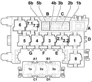
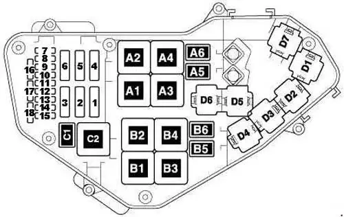
Relay and fuse carrier centre dash panel
{banner_news2}
| No. | A | Description |
|---|---|---|
| B | - | - |
| C | 30 | USA: Trailer detector control unit Brake booster |
| D | 30 | Control unit for seat adjustment and steering column adjustment with memory function Control unit for front passenger seat adjustment with memory function |
| E | - | - |
| F | - | - |
| G | - | - |
| 1b | 40 | Fresh air blower |
| 2b | 40 | ABS control unit |
| 3b | 40 | Rear fresh air blower |
| 4b | 40 | Heated rear window |
| 5b | 15 | June 2007→: Rear window wiper motor |
| 6b | 5 | June 2007→: Left washer jet heater element Right washer jet heater element |
| A1 | - | - |
| B1 | - | - |
| C1 | - | - |
| D1 | - | - |
| Relay | ||
| 1 | Adaptive suspension compressor | |
| 2.1 | Terminal 75x voltage supply | |
| 2.2 | Dual tone horn | |
| 3 | Headlight washer system | |
| 4 | Brake light suppression | |
| 5 | - | |
| 6 | Heated rear window relay | |
| 7.1 | V6 TDI/FSI, V8 MPI/FSI, V12 TDI: Continued coolant circulation (V6 FSI (June 2009→)) | |
| June 2010→(3.0 TDI generation 2): Coolant shut-off valve | ||
| 7.2 | June 2010→: Relay for automatic anti-dazzle interior mirror (only models with 8-speed automatic gearbox) | |
| 8 | Gearbox hydraulic pump relay | |
| 1a | - | |
| 2a | - | |
| 3a | - | |
Fuse assignment in fuse box, on right in luggage compartment
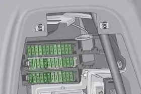
{banner_news3}
| No. | A | Description |
|---|---|---|
| Fuse carrier 6 | ||
| 1 | 15 |
→May 2010: Signal system control unit
|
| 15 | June 2010→→: Multimedia system control unit | |
| 2 | 30 | Control unit for reducing agent metering system |
| 3 | 15 | →May 2010: Adaptive suspension control unit |
| 5 | June 2012→: Reducing agent tank flap switch | |
| 4 | 5 | →May 2010: Reversing camera system control unit Reversing camera |
| 5 | 5 | Control unit for parking aid |
| 6 | 15 | Comfort system central control unit 2 |
| 7 | 15 | Comfort system central control unit 2 |
| 8 | 5 | Remote control receiver for auxiliary heater |
| 9 | 20 | 12 V socket 5 |
| 10 | 20 | Comfort system central control unit |
| 11 | 15 | Aerial reader unit for keyless entry system |
| 12 | 30 | Comfort system central control unit |
| Fuse carrier 5 | ||
| 1 | 15 | Signal system control unit |
| 2 | 5 | Operating unit for special signals |
| 3 | 15 | Two-way radio cut-off relay Two-way radio |
| 4 | 15 | Two-way radio cut-off relay Two-way radio |
| 5 | 5 | Radio |
| 15 | June 2010→→: Signal system control unit | |
| 6 | 5 | →June 2009: TV tuner |
| 7 | 5 | →June 2009: Navigation system with CD drive control unit - |
| 8 | 30 | →June 2009: Digital sound package control unit |
| 9 | 5 | →June 2009: Digital radio |
| 10 | 30 | →June 2009: Digital sound package control unit 2 - |
| 11 | 5 | →June 2009: Reversing camera system control unit →June 2009: Reversing camera |
| 12 | - | - |
| Fuse carrier 4 | ||
| 1 | 5 | June 2009→ May 2010: Radio |
|
7,5
|
June 2010→: Digital sound package control unit | |
|
30
|
June 2010→: Digital sound package control unit | |
| 2 | 5 | June 2009→: TV tuner |
| 5 | June 2011→: Digital TV tuner |
|
| 3 | 30 | June 2009→: Digital sound package control unit |
| 4 | 30 | June 2009→: Digital sound package control unit 2 |
| 5 | 15 | November 2007 → May 2010: Rear Seat Entertainment (9WP, 9WK) |
| 15 | →May 2010: Multimedia system control unit | |
| 15 | June 2010→: Adaptive suspension control unit | |
| 6 | 20 | Comfort system central control unit |
| 7 | 30 | Rear lid control unit Motor in rear lid control unit |
| 8 | 30 | Rear lid control unit 2 Motor in rear lid control unit 2 |
| 9 | 15 | Trailer detector control unit |
| 10 | 15 | Trailer detector control unit |
| 20 | June 2007→: Trailer detector control unit | |
| 11 | 15 | Trailer detector control unit |
| 20 | June 2007→: Trailer detector control unit | |
| 12 | 30 | Trailer detector control unit |
| 25 | June 2007→: Hinged tow attachment ball head motor Trailer detector control unit |
|
| Relay | ||
| 1 | - | |
| 2 | - | |
| 3 | November 2007→: 6-pin, connector -T6am-, for Rear Seat Entertainment | |
Fuse assignment in fuse box, under driver seat
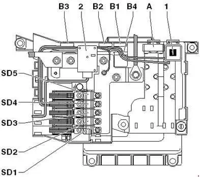
| No. | A | Description |
|---|---|---|
| 2 | - | Battery isolation igniter |
| A | 40 | Self-levelling suspension fuse |
| B1 | 30 | June 2010→: Fuse 1 (30) |
| B2 | 5 | June 2008→: Fuse for vehicle location system |
| B3 | - | - |
| B4 | 30 | June 2010→→: Fuse 2 (30) |
| SD1 | 150 | Fuse 1 on fuse holder D |
| SD2 | 125 | →May 2006: Fuse 2 on fuse holder D |
| SD2 | 150 | June 2006→: Fuse 2 on fuse holder D |
| SD3 | 50 | Fuse 3 on fuse holder D |
| SD4 | 60 | Fuse 4 on fuse holder D |
| SD5 | 125 | Fuse 5 on fuse holder D |
| Relay | ||
| 1 | Terminal 15 voltage supply | |
Relay and fuse carrier in electronics box engine compartment (petrol engine)
{banner_news}
| No. | A | Description |
|---|---|---|
| 1 |
40
|
Radiator fan |
|
60
|
Radiator fan | |
| 2 | 50 | Secondary air pump motor |
| 3 | - | - |
| 4 |
40
|
Radiator fan 2 |
|
60
|
Radiator fan 2 | |
| 5 | 50 | Motor for secondary air pump 2 |
| 6 | - | - |
| 7 | 30 | Ignition coils |
| 20 | June 2010→: Ignition coils | |
| 8 | 5 | Radiator fan control unit Radiator fan control unit 2 |
| 9 | 15 | Engine control uni Injectors |
| 10 | 10 | BAR, BHK, BHL: High-pressure sender (BAR) Coolant circulation pump (BAR) Map-controlled engine cooling system thermostat (BAR) Continued coolant circulation relay (BAR) Camshaft control valve 1 Camshaft control valve 2 (BAR) Intake manifold flap valve (BAR) Exhaust camshaft control valve 1 Exhaust camshaft control valve 2 (BAR) Intake manifold flap valve 2 (BAR) |
| 10 | CJTC, CJTB, CJWB, CNAA, CJWC, CTWA, CTWB, CJWE: High-pressure sender Camshaft control valve 1 Camshaft control valve 2 Charge air cooling pump |
|
| 11 | 5 | Engine control unit Air mass meter (BHK, BHL) |
| 12 | 5 | Crankcase breather heater element |
| 13 | 15 | BAR, BHK, BHL: Air mass meter (BAR) Air mass meter 2 (BAR) Activated charcoal filter solenoid valve 1 Secondary air inlet valve (BAR) Fuel metering valve Intake manifold flap valve (BHK, BHL) Secondary air inlet valve 2 (BAR) Fuel metering valve 2 (BAR) |
| 15 | CJTC, CJTB, CJWB, CNAA, CJWC, CTWA, CTWB, CJWE: Secondary air inlet valve Intake manifold flap valve Secondary air inlet valve Oil pressure control valve Continued coolant circulation pump Fuel system diagnostic pump Crankcase breather system shut-off valve |
|
| 14 | 15 | Lambda probe Lambda probe 2 |
| 15 | 15 | Lambda probe downstream of catalytic converter Lambda probe 2 downstream of catalytic converter |
| 16 | 30 | Fuel pump control unit |
| 17 | 5 | Engine control unit |
| 18 | 15 | BAR, BHK, BHL: Vacuum pump for brakes |
| Relay | ||
| A1 | →June 2009: Starter motor |
|
| June 2009→: Engine component current supply | ||
| A2 | →June 2009: Starter motor relay 2 |
|
| June 2009→: Motronic current supply | ||
| A3 | →June 2009: Engine component current supply |
|
| A4 | BAR, CJTC, CJTB, CJWB, CNAA, CJWC, CTWA, CTWB, CJWE: Secondary air pump |
|
| A5 | →June 2009: Brake servo |
|
| June 2009→: Starter motor | ||
| A6 | →June 2009: Continued coolant circulation |
|
| June 2009→: Starter motor relay 2 | ||
| B1 | - | |
| B2 | - | |
| B3 | →June 2009: Fuel pump | |
| B4 | - | |
| B5 | →June 2009: Fuel cooling pump | |
| B6 | - | |
| C1 | BAR: Circulation pump |
|
| BHK, BHL: Brake servo |
||
| CJTC, CJTB, CJWB, CNAA, CJWC, CTWA, CTWB, CJWE: Auxiliary coolant pump |
||
| C2 | →June 2009: Motronic current supply | |
3.0 TFSI V6:
- CJTC - 272 hp
- CJTB - 333 hp
- CJWB - 333 hp
- CJWC - 272 hp
- CJWE - 280 hp
- CNAA - 333 hp
- CTWA - 333 hp
- CTWB - 280 hp
3.6 FSI VR6:
- BHK - 280 hp
- BHL - 280 hp
4.2 FSI V8:
- BAR - 350 hp
Relay and fuse carrier in electronics box engine compartment (diesel engine)
{banner_news2}
| No. | A | Description |
|---|---|---|
| 1 | 60 | Radiator fan control unit Radiator fan |
| 2 | 80 | Automatic glow period control unit |
| 3 | 40 | CCMA & CATA without particle sensor: Heater element for auxiliary air heater (400 W) |
| 4 | 40 | Models without trailer towing attachment: Radiator fan control unit 2 Radiator fan 2 |
| 60 | Models with trailer towing attachment: Radiator fan control unit 2 Radiator fan 2 |
|
| 5 | 80 | CCFA, CCGA, BTR, CCFC: Glow period control unit 2 |
| 60 | CLZB & CNRB (June 2012→): Relay for 3rd heat setting |
|
| 6 | 80 | CCMA, CATA: Heater element for auxiliary air heater (2 x 400 W) |
| 60 | (CCMA & CATA June 2012→), CLZB, CNRB: Heater element for auxiliary air heater (2 x 400 W) |
|
| 7 | 15 | CCGA, CASA, CASB, CCFA, CCFC: Automatic glow period control unit Throttle valve module (CCGA, CASA, CASB) Exhaust gas recirculation cooler changeover valve Oil pressure control valve (CCFA, CCFC) Cylinder head coolant valve (CCFC) |
| 15 | CJGA, CJMA, CJGC, CJGD, CRCA, CNRA: Map-controlled engine cooling system thermostat Automatic glow period control unit Exhaust gas recirculation cooler changeover valve Electro-hydraulic engine mounting solenoid valve Oil pressure control valve Cylinder head coolant valve |
|
| 15 | CLZB, CNRB: Map-controlled engine cooling system thermostat Automatic glow period control unit Low heat output relay High heat output relay Exhaust gas recirculation cooler changeover valve Electro-hydraulic engine mounting solenoid valve Oil pressure control valve Cylinder head coolant valve |
|
| 15 | CCMA, CATA: Automatic glow period control unit Throttle valve module Low heat output relay High heat output relay Control unit for charge air cooler bypass Exhaust gas recirculation cooler changeover valve Exhaust gas recirculation cooler changeover valve 2 Oil pressure control valve |
|
| 15 | BTR: Automatic glow period control unit Turbocharger 2 control unit Exhaust gas recirculation cooler changeover valve Intake manifold flap motor |
|
| 15 | BUN, BUG: Automatic glow period control unit Turbocharger 1 control unit Exhaust gas recirculation valve Exhaust gas recirculation cooler changeover valve Intake manifold flap motor Motor for intake manifold flap 2 |
|
| 8 | 5 | Radiator fan control unit Radiator fan control unit 2 |
| 9 | 15 | Engine control unit Engine control unit 2 (CCFA, CCGA, BTR, CCFC) |
| 10 | 10 | Fuel pressure regulating valve Fuel metering valve Fuel metering valve 2 (CCGA) Fuel pressure regulating valve 2 (CCGA) |
| 11 | 15 | Lambda probe Lambda probe 2 (CCFA, CCGA, BTR, CCFC) Lambda probe heater Lambda probe 2 heater (CCFA, CCGA, BTR, CCFC) |
| 10 | CJGA, CJMA, CJGC, CJGD, CRCA, CNRA, (CCMA & CATA June 2010→): Lambda probe Lambda probe heater |
|
| 12 | 10 | CLZB & CNRB with particle sensor: NOx sender control unit NOx sender 2 control unit Particle sensor |
| 5 | Models without particle sensor: Fuel cooling pump relay (CCFA, CCGA, BTR) NOx sender control unit (CLZB, CNRB) NOx sender 2 control unit ((CCMA & CATA June 2010→), CLZB, CNRB) Fuel cooling pump (CCFA, BTR) Exhaust gas recirculation cooler pump (CCFA, CCGA, CCFC) |
|
| - | BUN, BUG, CASA, CASB, CJGA, CJMA, CJGC, CJGD, CRCA, CNRA: Not used |
|
| 5 | CCMA & CATA (→May 2010): NOx sender control unit NOx sender 2 control unit |
|
| 13 | 10 | High-pressure sender Continued coolant circulation relay Fuel cooling pump relay (BUN, BUG, CASA, CASB) Glow period control unit 2 (CCFA, BTR, CCFC) Coolant circulation pump Continued coolant circulation pump (CASA, CASB, CCFC, (CCMA & CATA June 2010→)) Fuel cooling pump (BUN, BUG, CASA, CASB) Motor for intake manifold flap 2 (BTR) Exhaust gas recirculation cooler pump (CASA, CASB) |
| 15 | (CCMA, CATA →May 2010), CCGA: High-pressure sender Continued coolant circulation relay Fuel cooling pump relay (CCMA, CATA) Exhaust gas recirculation cooler change-over valve 2 (CCGA) Coolant circulation pump Continued coolant circulation pump (CCMA, CATA) Fuel cooling pump (CCMA, CATA) Motor for intake manifold flap 2 Exhaust gas recirculation cooler pump (CCMA, CATA) |
|
| 14 | 5 | Air mass meter Air mass meter 2 (CCFA, CCGA, BTR, CCFC) |
| 15 | 5 | Engine control unit Engine control unit 2 (CCFA, CCGA, BTR, CCFC) |
| 16 | 20 | Fuel system pressurisation pump |
| 25 | CJGA, CJMA, CJGC, CJGD, CRCA, CNRA, CCFC, CLZB, CNRB: Fuel pump control unit |
|
| 17 | 20 | CCGA, BTR, BUN, BUG, CASA, CASB: Fuel pump |
| 10 | →May 2010 (CCMA, CATA): Pressure sender for reducing agent metering system Reducing agent pump Heater for reducing-agent pump |
|
| 5 | CJGA, CJMA, CJGC, CJGD, CRCA, CNRA, CCFC, CLZB, CNRB, (CCMA & CATA June 2010→): Engine control unit Engine control unit 2 (CCFC) |
|
| 18 | 7.5 | CCFA, CCGA, BTR, CCFC: Crankcase breather heater element Crankcase breather heater element 2 (except BTR) |
| 20 | (CCMA & CATA →May 2010), CASA, CASB: Relay for supplementary fuel pump Supplementary fuel pump |
|
| 10 | CCMA, CATA, CLZB, CNRB: Pressure sender for reducing agent metering system Reducing agent pump Heater for reducing-agent pump |
|
| 5 | June 2010→ (CCMA, CATA, CLZB, CNRB): Pressure sender for reducing agent metering system Reducing agent pump Heater for reducing-agent pump |
|
| Relay | ||
| A1 | Automatic glow period control unit | |
| A2 | →June 2009 (V12): Starter motor | |
| June 2009→: Terminal 30 voltage supply |
||
| A3 | CCGA, CCFA, CCFC, V12: Glow period control unit 2 | |
| A4 | →June 2009; V12: Starter motor relay 2 | |
| June 2009→ (CCMA, CATA): Relay for supplementary fuel pump |
||
| A5 | June 2009→: Starter motor | |
| A6 | →June 2009: Relay for supplementary fuel pump | |
| June 2009→: Starter motor relay 2 | ||
| B1 | CCMA, CATA, CLZB, CNRB: Low heat output | |
| B2 | - | |
| B3 | →June 2009: Fuel pump | |
| June 2009→ (CLZB, CNRB): Relay for 3rd heat setting |
||
| B4 | CCMA, CATA, CLZB, CNRB: High heat output | |
| B5 | →June 2009 (V12): Fuel cooling pump | |
| June 2009→ (CCFA): Fuel pump for auxiliary heater | ||
| B6 | CCGA, V12: Auxiliary coolant pump | |
| C1 | →June 2009 (V12): Fuel pump relay for auxiliary heater | |
| June 2009→ (CCMA, CATA, CCFA): Fuel cooling pump |
||
| C2 | →June 2009; V12: Terminal 30 voltage supply | |
| June 2009→ (CCFA): Fuel pump | ||
3.0 TDI V6:
- BUN - 211 hp
- BUG - 233 hp
- CASA - 240 hp
- CASB - 211 hp
- CATA - 225 hp
- CCMA - 240 hp
- CJGA - 240 hp
- CJGC - 204 hp
- CJGD - 245 hp
- CJMA - 204 hp
- CLZB - 245 hp
- CNRA - 225-240 hp (?)
- CNRB - 245 hp
- CRCA - 245 hp
4.2L TDI V8:
- BTR - 326 hp
- CCFA - 340 hp
- CCFC - 340 hp
6.0L V12:
- CCGA - 500 hp