2011-2018 Chevrolet Orlando - fuses
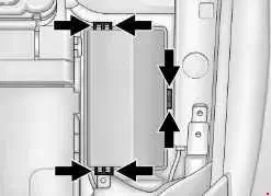
Engine compartment fuse box
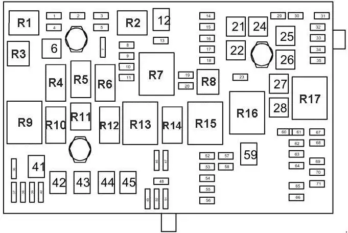
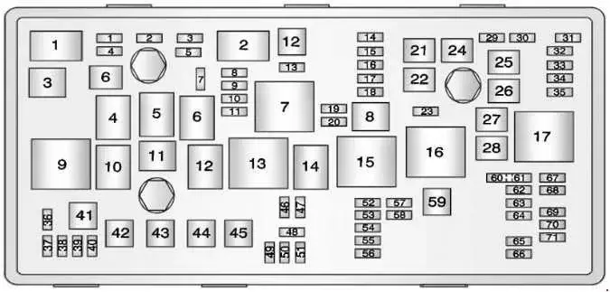
| No. | A | Description |
|---|---|---|
| 1 | 15 | Transmission Control Module |
| 2 | 15 | Engine Control Module |
| 3 | - | - |
| 5 | 15 | Transmission Control Module, Engine Control Module, Mass Air Flow/Intake Air Temperature Sensor, Output Speed Sensor |
| 6 | 30 | Windshield Wiper Relays |
| 7 | - | - |
| 8 | 15 | Fuel injectors |
| 9 | 15 | Ignition Coil, Fuel Injectors |
| 10 | 15 | Engine Control Module, Output Speed Sensor |
| 11 | 10 | Heated Oxygen Sensors |
| 12 | 30 | Starter Motor |
| 13 | 7.5 | Evaporative Emission (EVAP) Canister Vent Solenoid Valve |
| 14 | - | - |
| 15 | Rear Wiper | |
| 16 | 7.5 | Air Quality Sensor |
| 17 | 5 | Inflatable Restraint Sensing and Diagnostic Module |
| 18 | 10 | Fuel Pump Control Module |
| 19 | - | - |
| 20 | 20 | Fuel Pump Relay |
| 21 | 30 | Windows Motors, Front Door |
| 22 | - | - |
| 23 | - | - |
| 24 | 30 | Windows Motors, Front Door |
| 25 | Electronic Vacuum Pump | |
| 26 | 40 | Electronic Brake Control Module (EBCM) |
| 27 | 30 | Remote Control Door Lock Receiver |
| 28 | 40 | Rear Demister Grid |
| 29 | - | - |
| 30 | 15 | Electronic Brake Control Module (EBCM) |
| 31 | 20 | Body Control Module |
| 32 | 20 | Body Control Module |
| 33 | 30 | Heated Seat Control Module |
| 34 | 25 | Sunroof Control Module |
| 35 | 30 | Audio Amplifier |
| 36 | - | - |
| 37 | 10 | Headlamp - Right Main beam |
| 38 | 10 | Headlamp - Left Main beam |
| 39 | - | - |
| 40 | - | - |
| 41 | - | - |
| 42 | 20 30 |
Cooling Fan Relays, Cooling Fan Motor |
| 43 | - | - |
| 44 | - | - |
| 45 | 30 40 |
Cooling Fan High Speed Relay, Cooling Fan Motor |
| 46 | 10 | Cooling Fan Relays |
| 47 | 10 | Heated Oxygen Sensors, Throttle Body |
| 48 | 15 | Fog Lights, Front |
| 49 | - | - |
| 50 | - | - |
| 51 | 15 | Horn |
| 52 | 5 | Instrument Cluster |
| 53 | 10 | Inside Rearview Mirror |
| 54 | 5 | Headlamp Switch, Electrical Auxiliary Heater, HVAC Control Module |
| 55 | 7.5 | Window Switches, Front, Mirror Switch |
| 56 | 15 | Windscreen Washer Pump |
| 57 | 15 | Steering Column Lock Control Module |
| 58 | - | - |
| 59 | 30 | Fuel Heater |
| 60 | 7.5 | Outside Rearview Mirrors |
| 61 | Mirror Defogger | |
| 62 | 10 | A/C Compressor Clutch Relay, A/C Compressor Clutch |
| 63 | Rear Window Sensor | |
| 64 | 5 | Inflatable Restraint Sensing and Diagnostic Module |
| 65 | Rear Fog Lamp | |
| 66 | Rear Washer | |
| 67 | 20 | Fuel Pump Control Module |
| 68 | - | - |
| 69 | 5 | Body Control Module |
| 70 | 5 | Rain Sensor |
| 71 | - | - |
| Relays | ||
| 1 | A/C Compressor Clutch | |
| 2 | Starter | |
| 3 | Cooling Fan | |
| 4 | Windshield Wiper Speed Control | |
| 5 | Windshield Wiper | |
| 6 | - | |
| 7 | Powertrain | |
| 8 | Fuel Pump | |
| 9 | Cooling Fan Medium Speed 1 | |
| 10 | Cooling Fan Medium Speed 2 | |
| 11 | - | |
| 12 | Cooling Fan Speed Control (Or in Relay Block - Under-bonnet) | |
| 13 | Cooling Fan High Speed Relay | |
| 14 | - | |
| 15 | Ignition Main Relay | |
| 16 | Fuel Heater Relay | |
| 17 | Rear Window Defogger | |
| Note: Relays listed below are non-serviceable Printed Circuit Board (PCB) relays and are internal to the block. | ||
| - | Horn Relay | |
| - | Windscreen Washer Pump Relay | |
| - | Front Fog Lamp Relay | |
| - | Headlamp High Beam Relay | |
Instrument Panel Fuse Block
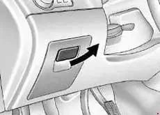
1) Open the storage compartment by pulling out at the top.
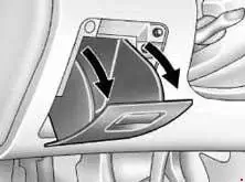
2) Squeeze the sides of the compartment in and rotate it downward.
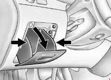
3) Remove the compartment.
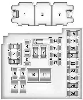
| No. | A | Description |
|---|---|---|
| 1 | 10 | Mobile Telephone Control Module |
| 2 | - | DC/DC Converter |
| 3 | 25 | Body Control Module |
| 4 | 20 | Radio |
| 5 | 7.5 | Parking Assist Control Module, Power Sounder, Multifunction Switch - Centre Console, Display |
| 6 | 20 | Cigar Lighter |
| 7 | 20 | Power Outlet |
| 8 | 30 | Body Control Module |
| 9 | 30 | Body Control Module |
| 10 | 30 | Body Control Module |
| 11 | 40 | Blower Motor Control Module |
| 12 | - | - |
| 13 | 25 | Heated Seat Control Module |
| 14 | 7.5 | Data Link Connector, Oil Feeding Connector |
| 15 | 10 | Inflatable Restraint Sensing and Diagnostic Module |
| 16 | 10 | Rear Compartment Lid Release Relay |
| 17 | 15 | HVAC Control Module / HVAC Control Assembly |
| 18 | Trailer | |
| 19 | Battery Sensor | |
| 20 | - | - |
| 21 | 15 | Instrument Cluster |
| 22 | 2 | Ignition Switch |
| 23 | 20 | Body Control Module |
| 24 | 20 | Body Control Module |
| 25 | -- | - |
| 26 | 20 | Auxiliary Power Outlet |
| Note: Relays listed below are non-serviceable Printed Circuit Board (PCB) relays and are internal to the block | ||
| 1 | Tailgate Release Relay | |
| 2 | Logistic Mode Relay 1 | |
| 3 | Auxiliary Power Relay | |
Fuse box above battery
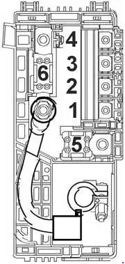
| No. | A | Description |
|---|---|---|
| 1 | 100 | Fuse Block - Instrument Panel |
| 2 | 100 | Fuse Block - Instrument Panel |
| 3 | 80 | Electrical Power Steering (EPS) (NJ1) |
| 4 | - | - |
| 5 | 250 | Fuse Block - Battery Auxiliary |
| 6 | 250 500 |
Starter Motor |
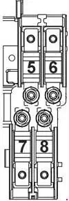
| No. | A | Description |
|---|---|---|
| 5 | 80 | Glow Plug Control Module |
| 6 | 100 | Electrical Auxiliary Heater |
| 7 | - | - |
| 8 | - | - |
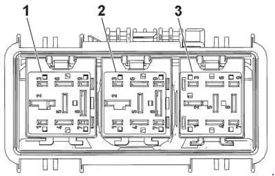
| No. | Description |
|---|---|
| 1 | Cooling Fan Left Medium Speed Relay |
| 2 | Cooling Fan Speed Control 2 Relay |
| 3 | Cooling Fan Right Medium Speed Relay |

